my 20v'ed ae86 swap "how to" write-up

Strictly 20valve engine related topics.

Moderators: dr.occa, CBR_TOY

Post Reply
User avatar
morgan
Member
Posts: 279
Joined: Thu Oct 18, 2012 11:28 am
Location: jersey

my 20v'ed ae86 swap "how to" write-up

Post by morgan »

theres a ton of threads about small things in general about this swap, so heres my attempt at a full, step-by-step instruction on how to do it starting with your ae86 GTS. theres going to be plenty of info links, pics, etc. if im missing something or youre unsure, ask away.
this is for BT electronics using a MAP sensor
*if you have an sr5, start here, and when you have converted, come on back over...
http://forums.club4ag.com/zerothread?id=6239
^big thanks to Andrew aka assassain10000 for that supreme write-up
-----------------------------------------------------------------------------------------------------------------------
PART 1-ORGANIZATION
*this step is key to any swap, or major work for that matter, that you are doing to your car. preparation is key, and makes things go smoothly...usually*
step 1-buy yourself a 20v. either Silvertop(ST) or a Blacktop(BT) will do.
ST-Image
BT-Image
you would be best off doing an overhaul to be sure gaskets and seals are in good working order(i will add part numbers at a later date for misc gaskets and seals, since some are cross-referenced to usdm cars).
-----------------------------------------------------------------------------------------------------------------------
step 2-start a checklist, one for parts needed, one for work needed.
*heres where it gets tricky. you need to figure out costs of parts/labor and see which options are best for you and your wallet*
parts needed
-tall block with ITB's
-20v engine harness
-GTS underdash harness
-pilot bearing for transmission input shaft(fwd doenst have this, need it for rwd) p/n 90363-12003
^[quote=Sam-Q]- A spigot bearing can be sourced from any bearing shop cheaply, just ask for a 6001-2RS[/quote]
-20v coil/ignitor(didnt get one with the motor? go to the jy and look for a mid 90's 4runner, grab the bracket too)
coil p/n 90919-02197
igniter p/n 89621-12050 (must have a large "201" in green writing on it)
-ISCV
-MAP sensor (if it didnt come with one, grab one at the jy from a 93/97 corolla. either 4afe or 7afe is fine. p/n 89420-02010)
-20v dist with cap and rotor(if using the oem ignition system-more on that later)
-VVT sensor
-TPS(doenst matter which you have for the swap-more on this later)
ST p/n 89452-12080 (same as 2JZGTE, 3RZFE, 2RZFE, 5VZFE)
BT p/n 89452-12080/22080
-O2 sensor (or buy one for a 1993 MR2 with the 3sgte motor, OBX sells one for about $60)
ST p/n 89465-19495 / 89465-12290
BT p/n 89465-19685
To Do
-put in pilot bearing
-freshen motor up
-drop in motor
-coolant flow(fwd w/water lines, or rwd w/stock gts parts-more on that later)
-spark(cut/smash firewall/dist relocation kit, COP conversio-more on this later)
-wiring(make your own/slice your own, Dr.Tweak, mr220v, send it to me...)
-fill w/oil and coolant

User avatar
morgan
Member
Posts: 279
Joined: Thu Oct 18, 2012 11:28 am
Location: jersey

Re: my 20v'ed ae86 swap "how to" write-up

Post by morgan »

PART 2-Motor Prep
-----------------------------------------------------------------------------------------------------------------------
now is whan you want to freshen the motor up. while its out of the car, do your maintanance. new HG, valve seals, water pump gaskets, etc...now is when you want to get machine work done. disassemble everything if needed, always good to check stuff.
an engine stand helps wonders. pick one up at Harbor Freight before you start for under $60. pays for itself after one use.
heres a link to the BT manual for reference on doing such work, proper torque sequence, etc, everything is in there...save this to your computer.
http://www.locost7.info/mirror/4age_blacktop.php
only problem with the BT manual, the instructions for setting your cam gears and timing belt is off. heres a thread i started to show you how to set it up correctly.
http://forums.club4ag.com/zerothread?id=87830
heres a write up i did on replacing your valve seals...
http://www.ectoyotas.com/%20fo...t=132
i recommend changing your timing belt at this point. if you have a BT, youre out of luck and need to source an oem one. have a ST? then go to your local parts store and order a Buick Skylark belt. ????! i know, but its true, im running one right now.
GoodYear #40081(can be cross-referenced to another manufacturer at your local auto parts store)
it costs about $20.
as for all other gaskets and seals, heres the p/n's...
****C.R.=cross referenceable to usdm parts***
BT engine overhaul gasket set 04111-16330
ST engine overhaul gasket set 04111-16210
BT HG 11115-16111
ST HG 11115-16110
BT/ST spark plug tube seal(4x) 11193-16010(C.R.)
BT/ST seal washer for valve cover bolts(3x) 90210-09016(C.R.)
BT valve cover gasket 11213-16021
ST valve cover gasket 11213-16020
BT/ST cam shaft oil seals-exhaust 90311-35013(C.R.)
-intake 90311-40016(C.R.)
BT rear main seal retainer gasket 11383-16010(C.R.)
ST rear main seal retainer gasket 11383-16010(C.R.)06/1991 to 04/1992
ST rear main seal retainer gasket 11383-16010(C.R.)05/1992 on...
BT/ST/16v rear main seal 90311-70007(C.R.)
BT/ST PVC valve cover grommet 90480-18001(C.R.)
BT/ST valve seals-intake 90913-02093(C.R.)
-exhaust 90913-02092(C.R.)
BT oil pump gasket 15197-15030
ST oil pump gasket 15197-15012(C.R.)
BT oil pump/crank seal 90311-32020(C.R.)
ST oil pump/crank seal 90311-32018(C.R.)
BT oil pump strainer gasket 15149-16010
ST oil pump strainer gasket 15149-15011(C.R.)06/1991 to 05/1992
ST oil pump strainer gasket 15149-16010(C.R.)06/1992 on...
BT/ST water pump housing gasket 16124-16040(possible C.R.)
16v rwd water pump housing gasket 16124-15010(usdm part)
BT/ST/16v rwd-water pump housing to block o-ring 96711-24035(C.R.)
BT ITB gasket to head 17177-16030
ST ITB gasket to head 17177-16020
BT exhaust mani gasket 17173-16030
ST exhaust mani gasket 17173-16020
BT/ST dist. cap 19101-16010
BT/ST dist. rotor 19102-16010
BT/ST dist. o-ring(seals to head) 90099-14091(C.R.)
BT/ST VVT cam gear to cam shaft o-ring 90301-14007(C.R.)
BT/ST injector-top/bottom insulators(8x) 23291-75010(C.R.)
-middle o-ring(4x) 90301-17007(C.R.)
-bottom o-ring(4x) 90301-14006(C.R.)
BT/ST spark plugs(4x) BKR6EP11 or PK20R11
16v rwd pilot bearing(NEEDED!) 90363-12003
theres also a cheap replacement oil filler cap by Stant, p/n-11113. cost me $7 at Pepboys and it works just like it should. http://shop.advanceautoparts.c....html
Image
-----------------------------------------------------------------------------------------------------------------------
get all this stuff done and assembled, and then engine prep. is complete. continue to bolt on anything that you can at this point... motor mounts, manifolds, pulleys/belts, dist.(if using one), coolant parts at rear of head, etc...
-----------------------------------------------------------------------------------------------------------------------
*dont forget to put in your pilot bearing, this is very important. go to toyota and get a new one. make sure you tap it in with a socket thats as big as the bearing! you dont want to put pressure on the small, inner race, of the ball bearing cover. only the outer race!
Image
*thanks to runkillerrabbit @c4ag for pic

heres another p/n reference thread by HASportAE86 @c4ag
http://forums.club4ag.com/zerothread?id=36977
parts reference/sensor info/"how to clean the ISCV" @ 4age20v.blogsome.com
http://4age20v.blogsome.com/ca...umber

User avatar
morgan
Member
Posts: 279
Joined: Thu Oct 18, 2012 11:28 am
Location: jersey

Re: my 20v'ed ae86 swap "how to" write-up

Post by morgan »

PART 3-Cooling
-----------------------------------------------------------------------------------------------------------------------
so theres 2 options on this...either keep the FWD flow and buy a water line kit, or change stuff around and go with a RWD flow. Its said that the FWD flow is better, the cold coolant from the radiator goes directly to the head and under the ITBs intake first, whereas the RWD flow lets the cold coolant into the water pump to the block first. The gains/looses are debatable, and each is "better" in its own respect, but in the end...it comes down to what you decide you want. Money plays a factor along with the purpose of the build and also if you do/dont want hard liines all over your bay. Priorities change between people, so im not saying to do either, you decide.

heres your options...
-----------------------------------------------------------------------------------------------------------------------
FWD Flow (how the motor is set up STOCK)

This is the option where you keep everything flowing like it was from the factory. although it sometimes means shelling out big bucks for the water line kits and moving things like your ISCV and other stuff. When done correctly, it looks clean, but you still have hardlines going all over the bay. You end up keeping the stock 20v water pump, exhaust side outlet, and the thermostat housing at the back of the head with all the stock sensors(or use the housing provided with the kit).

heres a link to the explanation of how the flow goes from the factory, along with a few other options.
http://www.toycrazy.net/tech/rwd20v.html

so you have a few aftermarket hardline kit options.
1. T3
2. SP Tec
3. SS Works
4. DIY
-----------------------------------------------------------------------------------------------------------------------
T3 http://technotoytuning.com/productdetail.php?p=780
T3 makes great products, and their customer service is par to none. you get to support real 86 enthusiasts, buy american made products/support the economy, and you wont have to wait months for the parts...usually. only problem with this kit-they leak, always! best fix is the Toyota "Oil Pan & Camshaft FIGP"
Image
^picture from T3 website
-----------------------------------------------------------------------------------------------------------------------
SP Tec
simple and straight forward. need to relocate the ISCV, with the included bracket.
Image
^picture from http://www.tokyoseven.com , see below...
buy here...
http://www.tokyoseven.com/T7/p...d=784
-----------------------------------------------------------------------------------------------------------------------
SS Works
this kit is legit. if i had the cash, this is what i would possibly be using. great reviews from everyone that gets it.
search for photos, every one i put up, dissappears after a few days
-----------------------------------------------------------------------------------------------------------------------

-----------------------------------------------------------------------------------------------------------------------
DIY Method
if you have access to mills and machining knowledge, build your own. you can also use the stock thermostat housing and ports, and run lines to the proper ports on the ae86 radiator, and go from there.

DIY links for ideas
http://forums.club4ag.com/zerothread?id=1684
http://www.my-acoustic.com/Car...r.htm
-----------------------------------------------------------------------------------------------------------------------

-----------------------------------------------------------------------------------------------------------------------

RWD Flow
you need a 16v water pump and backing plate, and to mod the upper water neck from the 20v that is right above the water pump. the flow will be different than the 20v had from the factory, with the cold coolant entering the water pump, then to the block first, unlike the 20v which it went to the head first. This rwd flow is said to cause cylinder #4 to overheat. While i didn't have a problem with it, i also haven't tracked my car yet. I would recommend a lower temp thermostat, 5 to 10 degrees lower. heres a pic of how the stock 86 rwd coolant flows.
Image
^thanks to http://www.billzilla.org for the pic

Sam_Q's stuff
good products, many options to get exactly what you want. heres a link to his thread on c4ag to his website. very knowledgable guy, and willing to help explain your options. want the best bang for your buck? buy from this guy!
http://forums.club4ag.com/zerothread?id=83506

the Mr.John of JSP Method
simple and effective. only problem i foresee with this is sensor location. going stand-alone? might not be such an issue then.
http://forums.club4ag.com/zerothread?id=1012

My Method
not perfect but functioning and proven to work. these are one-off pieces, im not in production, so sorry, dont ask please.

i used my 16v water pump, made a by-pass plate for the rear of the head with a port for the heater, an exhaust side block off plate, and an adapter to mount the stock 16v upper water neck to the 20v head to utilize the 20v sensors.

rear by-pass plate with heater outlet
Image
Image

16v upper water neck and adapter w/sensors
Image
Image
Image

welded a barb for the bypass tube...
Image

exhaust side block off plate
Image

16v backing plate
Image

hard line made from aw11 mr2 line to to from heater to backing plate
bottom pic is mr2 line, top is after cut and weld.
Image

heres how the upper water neck sits, just needed to find another hose that fit better since the port angles down a bit more.
Image
Image
Image<

User avatar
morgan
Member
Posts: 279
Joined: Thu Oct 18, 2012 11:28 am
Location: jersey

Re: my 20v'ed ae86 swap "how to" write-up

Post by morgan »

PART 4-Spark
-----------------------------------------------------------------------------------------------------------------------
theres a few options for this, i will go over 3.
1. stock location for the distributor(firewall needs to either have a sledge hammer taken to it or cut a hole in the firewall and weld in a new box to clear the dist.)
2. distributor relocation kit(moves it to the front of the engine, and has the exhaust cam drive it.)
3. Coil Over Plug conversion(aka COP, using some newer ignition options, and a waste spark firing system on a stock 20v ecu.)
-----------------------------------------------------------------------------------------------------------------------
-----------------------------------------------------------------------------------------------------------------------
1. stock dist. location/modification to the firewall
not always the choice option, but effective and cheapest. With the 20v dist. being at the back of the head, when orientated for a rwd car, the cap sticks out too far. you need the firewall in that area to be moved back about 2". easiest way a BFH, but it looks like sh!t. heres a pic of my 86 when i got it. the po had a 20v in it, and went to town on the car.
Image
even after some paint, i still couldnt stand this. didnt help that i had a 16v and a broken air box to change the vents for the fan.
Image
when i finally did the 20v swap, it "helped"...me be lazy. i just covered it with some dynamat type material to keep the exhaust fumes out. didnt work though, and still looked like sh!t.
Image
but at the end of the day, the dist. fit. only problem i had...getting it out if needed. i had to take the valve cover off, unbolt the cap holding the dist in place on the head, and unplug the wires. if that wasnt enough in such a small space, you then have to wiggle the dist. out and find the sweet spot. basically try every angle til you get it out, and repeat for installation. a real PITA.
Image
-----------------------------------------------------------------------------------------------------------------------
2. relocation kit
you can find yourself one of these kits, but be prepared to pay upwards of $700 new. heres what they look like installed.
Image
Garage Annex/SP Tec
Image
cant remember the name of this brand but im a little leary about this...
Image
only thing with these kits, you need to get different plug wires, since the stock ones arent long enough. i believe Sam_Q also makes his own kit, or its in the works.
-----------------------------------------------------------------------------------------------------------------------
3. COP conversion
while utilizing the stock coil for a tach signal, the stock igniter for the confirmation signal to the ecu, and a waste spark that works...this keeps you from shelling out $ for the relocation kit and you dont need to take the BFH to your car. pretty simple and straight forward.
heres a thread about all the different coils you can use and how to wire them.
http://forums.club4ag.com/zerothread?id=18900
i chose to go with the honduh d17 coils from a 2002-05 civic. (thanks Hector for the hook up)
how the stock 20v wiring is...
Image
this is how i wired the COP's into the harness...
Image
this is much cleaner and they fit under the plug cover. heres my current setup, after cutting out my entire firewall and welding in a new one that wasnt bashed in...
Image
Image
cleaner, and functional. some people have problems with the rpm's being limited to 4000 with the COP conversion, but it usually has to do with incorrect wiring.<

User avatar
morgan
Member
Posts: 279
Joined: Thu Oct 18, 2012 11:28 am
Location: jersey

Re: my 20v'ed ae86 swap "how to" write-up

Post by morgan »

PART 5-Fuel
there isnt really much to this. you need your stock gts in-tank fuel pump to be operational, and you might as well buy a new filter too. the stock ae86 feed line to the manifold isnt long enough, neither is the stock 20v line. so you can either cut them and add in a piece to lengthen it, or go with stainless braided lines.
-----------------------------------------------------------------------------------------------------------------------
Stainless Braided feed line
i read this thread below about it, seemed pretty easy. So i ordered up the materials from http://www.anplumbing.com and did it.
http://forums.club4ag.com/zerothread?id=40418
the fittings i got, 2 banjo bolts, makes it tough to get the line to go just right when the filter is in the stock location. then i ended up snapping a banjo bolt in half from over-tightening it, so i got some other parts and made a bracket to locate the filter higher up on the passenger side shock tower. just get crative, but be safe. it is gasoline afterall so lets try not to light our car on fire from a half-assed job. this is where quality really counts.
Image
Image
-------------------------------------------------------------------------------------------
by popular demand, heres the pressure gage parts i bought from summit racing...
*note*-i used a small o-ring on the banjo bolt up top to keep it centered in the Earl's fitting, you can see it in the pic of the banjo bolt. just push it all the way to the top so it doesnt impeed flow.
Image
Image
and heres the AN-fittings and stuff i bought(thanks to balmo for the info above and below)...
-Earl's banjo hose ends 807691ERL (buy 2 of these)
-3ft -6AN ss hose
Image<

User avatar
morgan
Member
Posts: 279
Joined: Thu Oct 18, 2012 11:28 am
Location: jersey

Re: my 20v'ed ae86 swap "how to" write-up

Post by morgan »

PART 6-Wiring
this can be the most overwhelming part of the build, if your a DIY'er like me. many just send the 20v engine harness and the 16v engine harness off to be done by a pro, at the cost of $350-700. Im not a pro, but i have experience and its proven since my car runs, and will do it if you need me to. PM me if your interested.
you have 2 options for that route. Dr Tweak of Pheonix Tuning or mr220v.
Dr Tweak...
http://forums.club4ag.com/zero...=4780
http://forums.club4ag.com/zerothread?id=13939
mr220v...
http://forums.club4ag.com/zero...=2434
http://forums.club4ag.com/zerothread?id=13573
-----------------------------------------------------------------------------------------------------------------------
now if your thorough with your work, have good research skills, soldering skills, wire diagram knowledge, lots of free time, and a desire to do this yourself, heres a simple walk through. but be warned! its not easy, if you feel that it might be too much, dont do it, you will cause more damage, and spend more money in the long run. but lucky you, you dont have to go searching all over for the info, heres my collection of stuff that made it possible for me to do it.
You will greatly benefit from owning an FSM for your car. the Haynes manual also has the wiring diagrams too if you cant get an FSM.
FSM=Factory Service Manual
-----------------------------------------------------------------------------------------------------------------------
all the 20v pigtails can be sourced at your local junkyard. along with the MAP sensor from the 1993-97 corolla and the IAT sensor from any 90's toyota. the ECU plugs from the same corolla, other 90's toyotas and the same era hondas too. i brought parts with me, had them marked so they knew i wasnt stealing them and so i didnt pay for them again, and just matched them up. i cut about 6" off so theres something to work with.
i also suggest if your building your own, to buy a sacraficial harness, i recommend the 1993-1997 corolla, since you can use a bunch of its pigtails, the MAP sensor and the IAT sensor, along with the ecu plugs.
-----------------------------------------------------------------------------------------------------------------------
this site is a guys diary of a swap in his aw11 mr2. really good info and pics.
http://www.padandwheels.com
link to all the pigtails for the motor and what wire is what...
http://padandwheels.com/mr2/bl....html
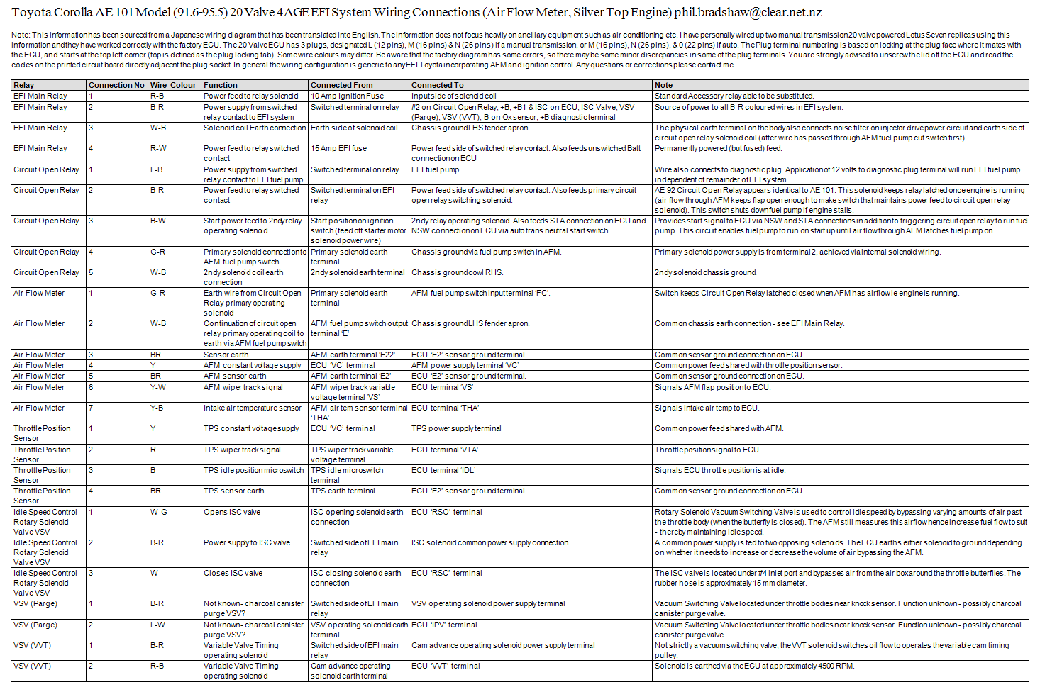
Silvertop wiring diagram. similar to the BT, but consider the difference from AFM and MAP. still good in seeing how things are done up. i printed this out huge, taped all the pages together, and put it on the wall of my garage.
http://media.photobucket.com/i...m.jpg
this is just a little diagram i found...
Image
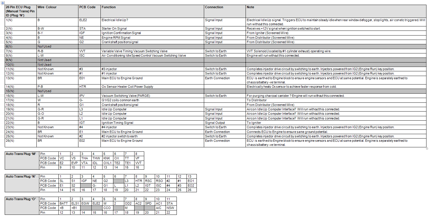
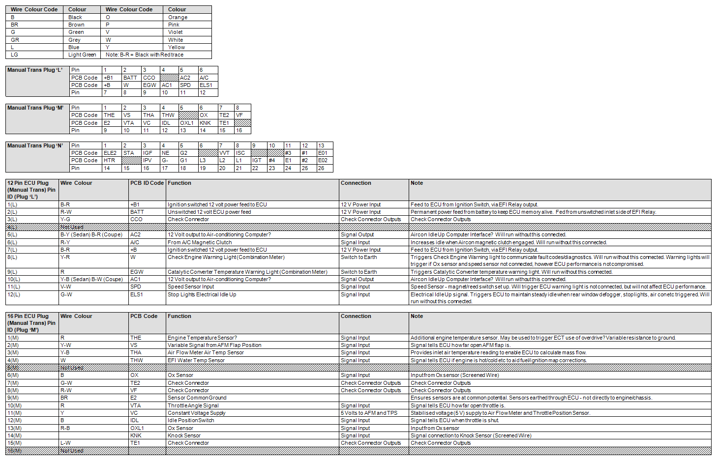
silvertop ecu pin-out(manual and auto)
http://4age20v.blogsome.com/20...inals/
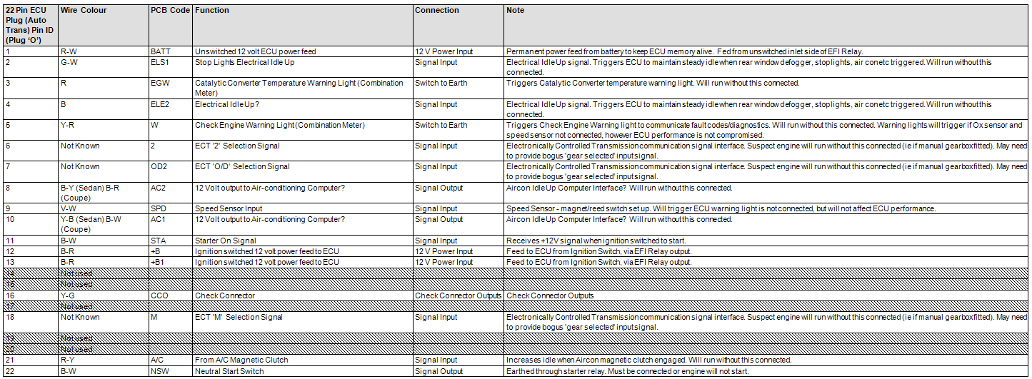
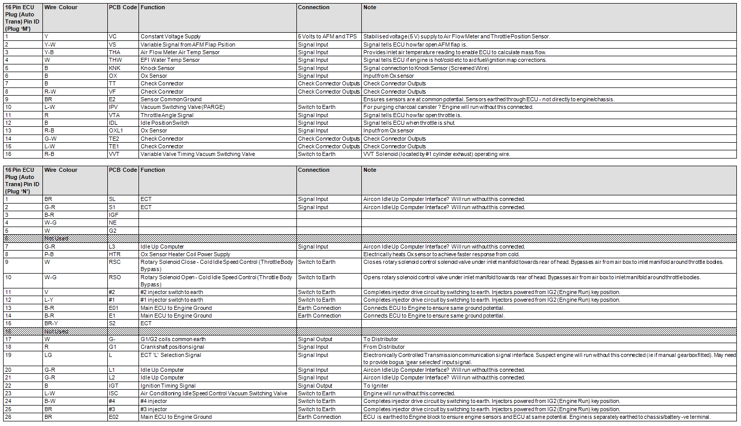
BT pin-out
Image
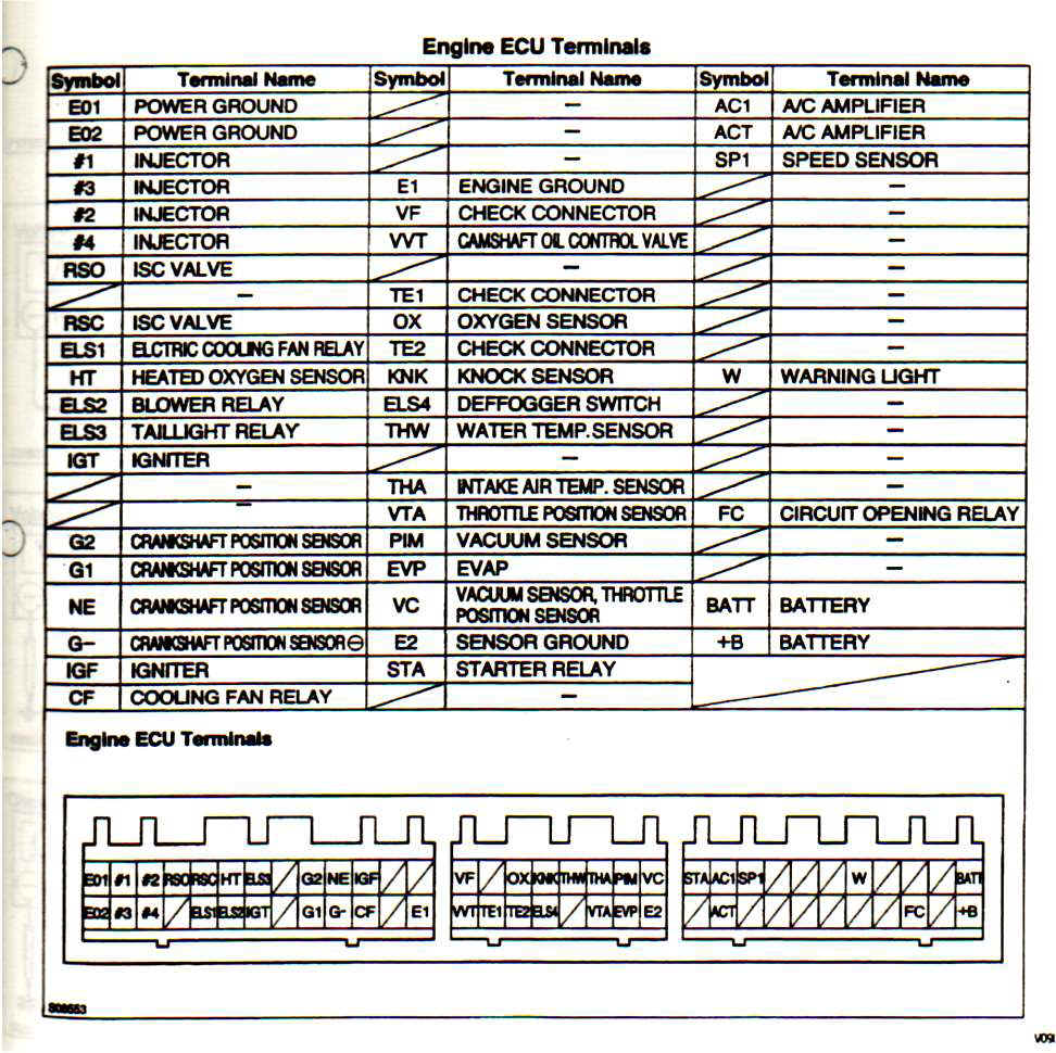
a full list of what each wire does. for an ST, but only difference from a BT is the AFM/MAP. really helpful...
http://www.docstoc.com/docs/24...-1999
the site this was on, now charges for downloads, so heres some pics of the pages. PM me if you want me to email you a .doc copy.
Image
Image
Image
Image
Image
read the REFERENCE section of club4ag. tons of info and pics to save and print out.
http://club4ag.com/technical_main.htm
-----------------------------------------------------------------------------------------------------------------------
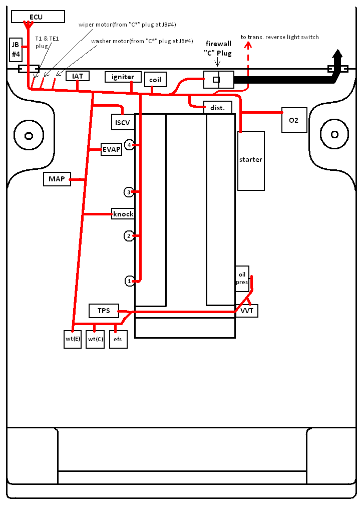
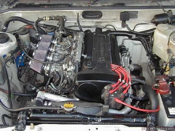
heres an overview of how i routed the wiring harness when it was all done.
Image
to do your own wiring, you need a few pigtails from your stock harness.
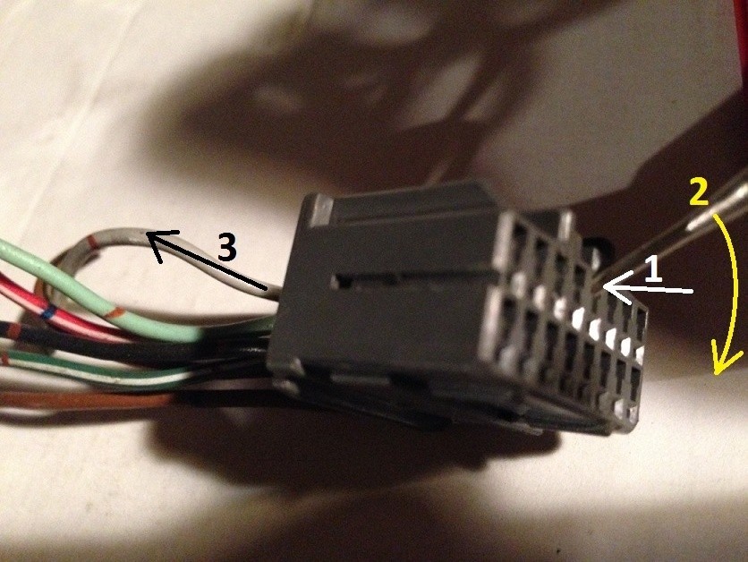
1. the "C" plug-the large black plug on the firewall
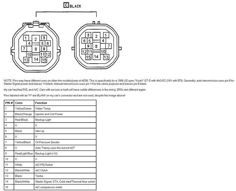
Image
*photo courtesy of Grant @ club4ag. http://www.vems.hu/wiki/index....iring

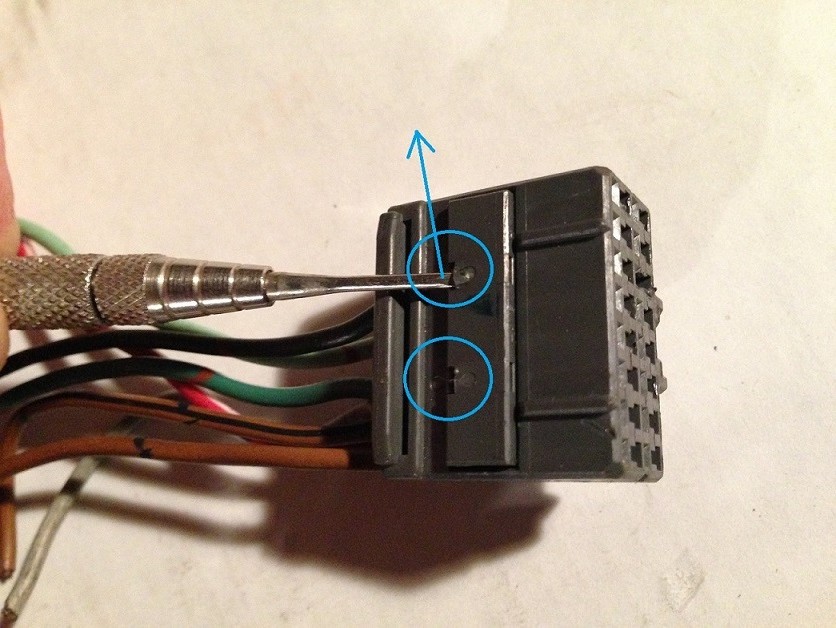
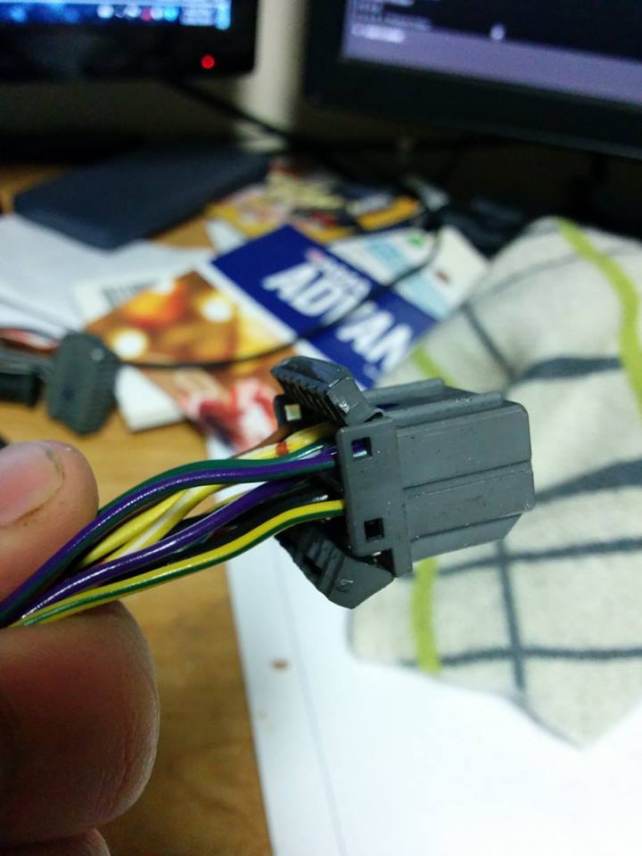
from the underdash harness, you need this plug which goes to the ECU, well call it the "T" Plug. more so, you need to cut the plug off and re-run some wires to the 20v ECU. the B+, SP1, and WARN wires.
- the B+(black with red dots) is from the EFI main relay and provides power to the ECU and some sensors
- the SP1 is the speed sensor(blue/white)
- the BATT wire to the 20v ECU plug(provides constant power to ECU even when car is off, for memory)
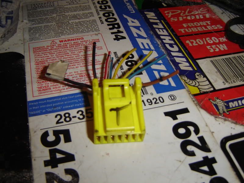
Image
*photo courtesy of nixeighty6 @clug4ag.com

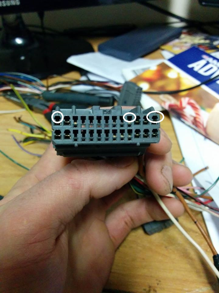
heres the locations, on the ECU, just imagine the plug in there and see which wires you need.
Image
*photo courtesy of club4ag.com Reference Section & Woody
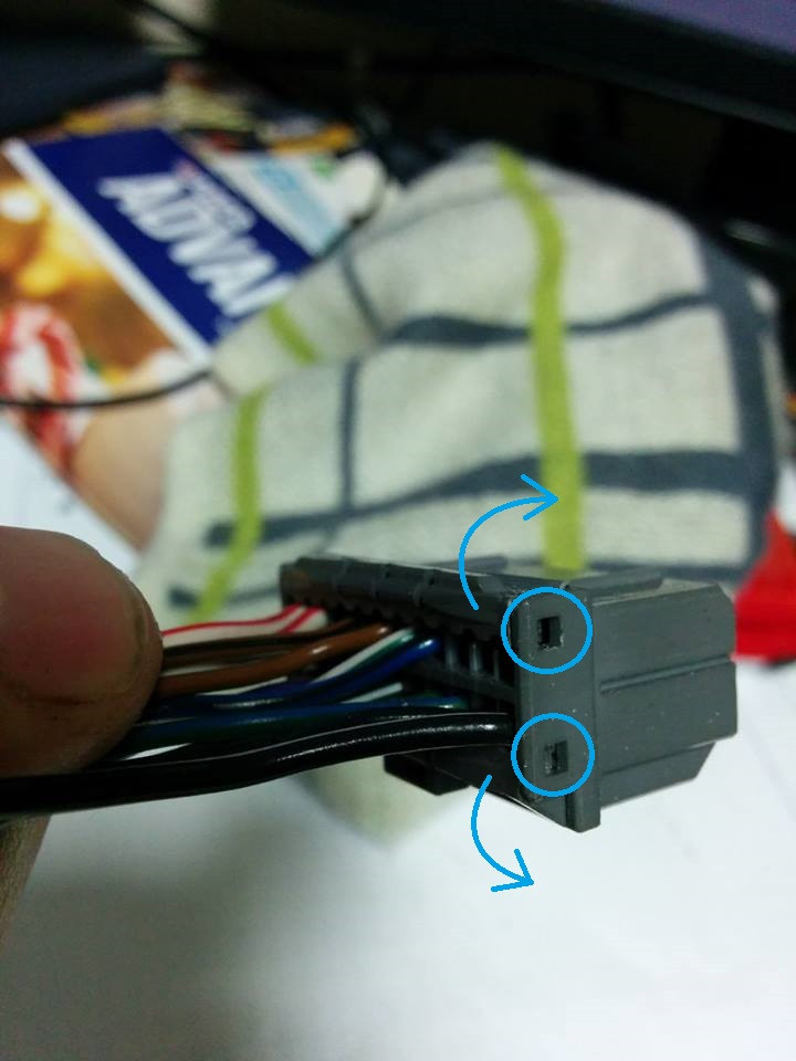
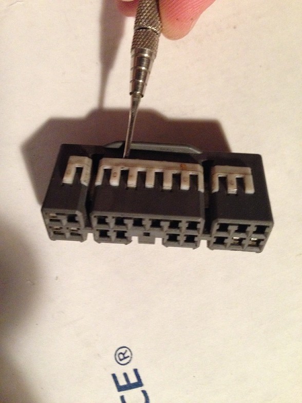
and the "C*
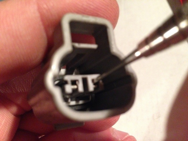
" plug, from the gts engine harness that plugs into Junction Box #4(JB#4) behind the passenger side kick panel. its the plug that im holding, you can see the difference between the other 2 for the ECU. what you want to do for this one is seperate the GTS harness and keep in tact the Wiper Motor and Washer Bottle Motor wires and pigtails and incorporate them into your 20v harness. you can cut the others, but dont cut the wiper/washer wires that are going directly to those 2 items, otherwise you get to solder those too, and why bother if its already complete. you also need to connect PIN#11(warning light)to the 20v ECU plug. the WARN or W(green/yellow) is the check engine light in the cluster. if you dont source a GTS cluster with this in it, wire up an LED or something.
Image
Image
-----------------------------------------------------------------------------------------------------------------------
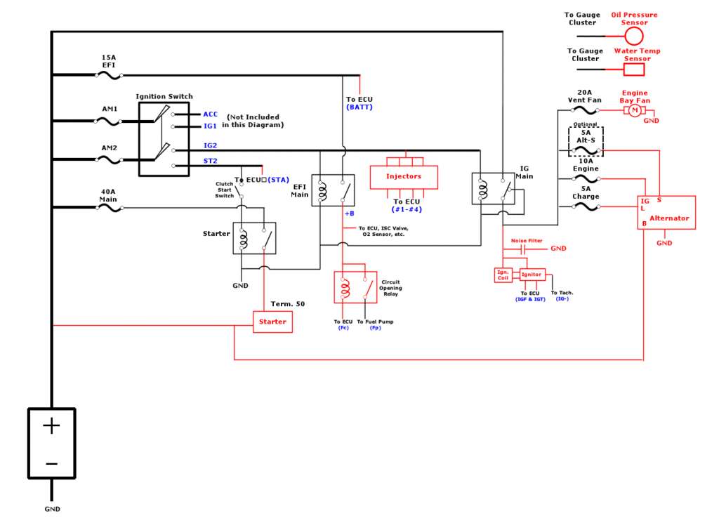
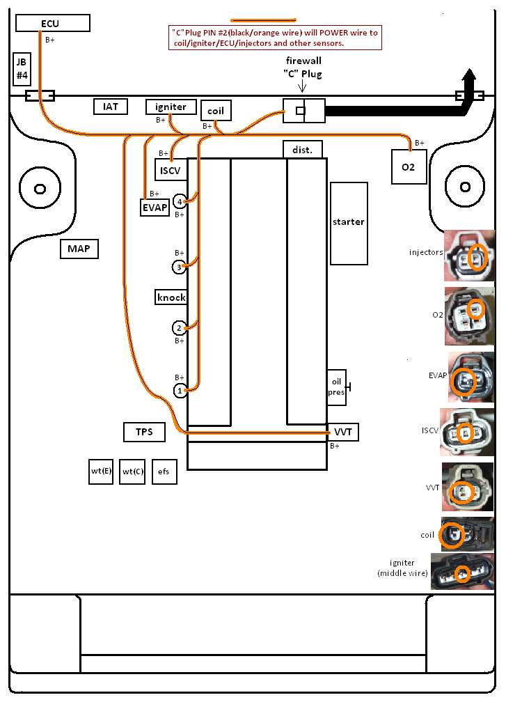
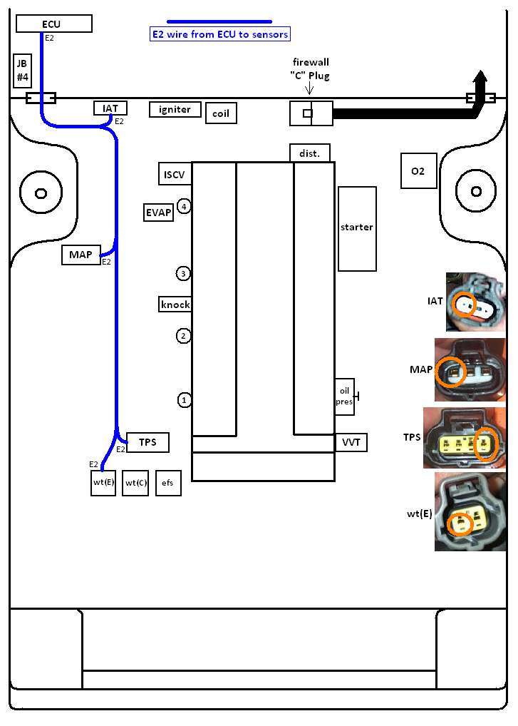
so heres a few diagrams i drew to help you through this...KEEP IN MIND THAT THE COLOR I CHOSE FOR EACH WIRE ISN'T NECESSARILY THE COLOR FROM A 20V HARNESS, its only so you can distinguish between each. and if your building your own harness, then who cares...on with the good stuff aka archaic drawings i provided. you can tell me you love me at any time...
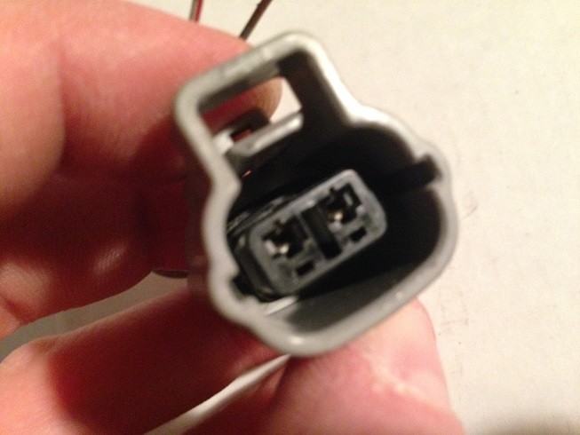
the POWER wire, for everything listed, comes from the "C" Plug PIN#2, with pics of the pigtails and the wires in question circled...
Image
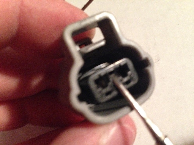
the E2 wire(sensor grounds-through the ECU) with pics of the pigtails and the wire in question circled...
Image
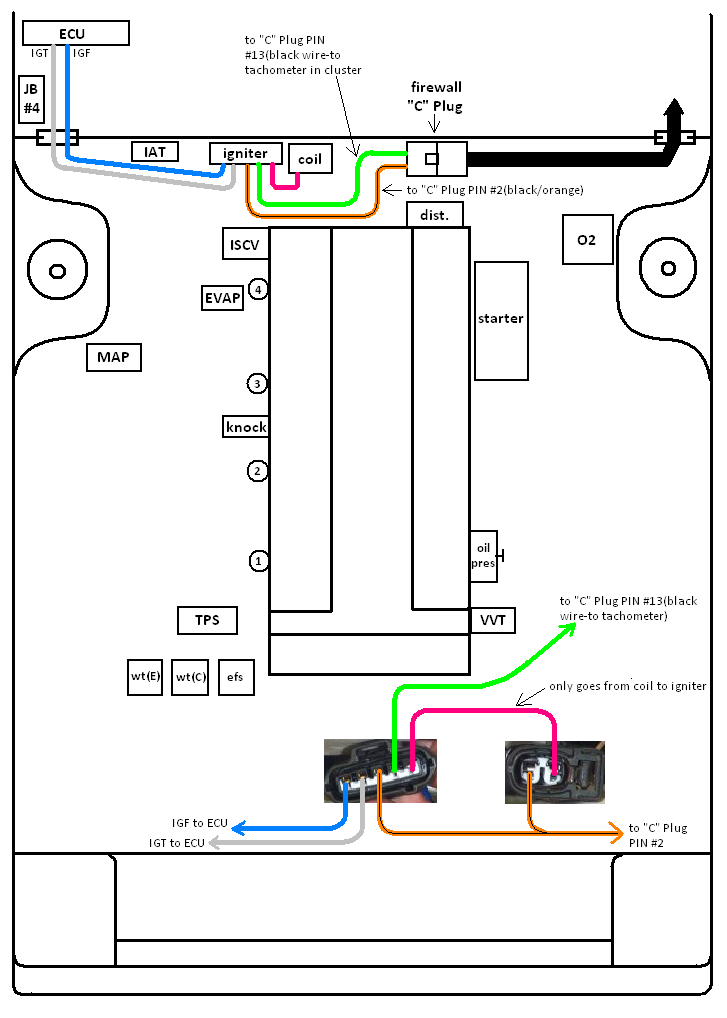
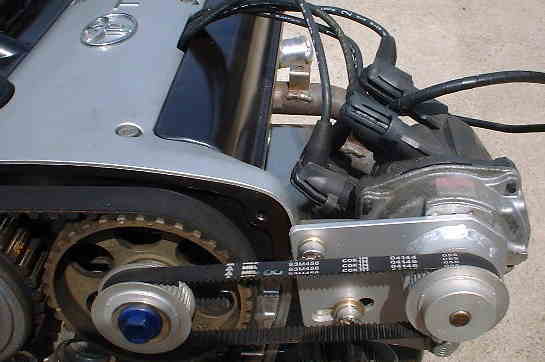
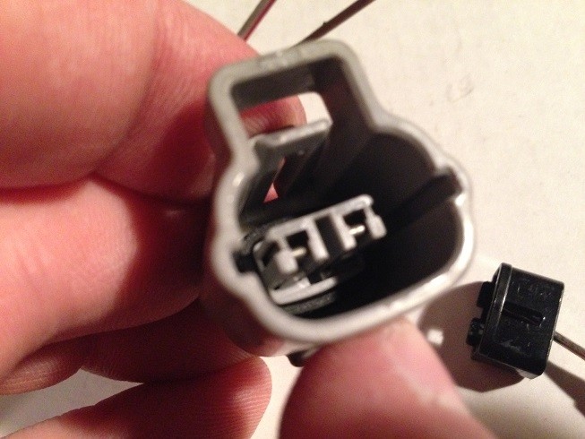
wiring the coil and igniter. on the bottom of the pic is the pigtails, and what each wire is...
Image
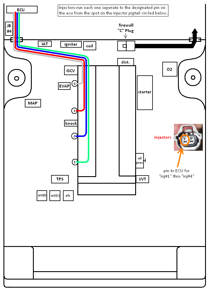
then the injectors, on the 20v ecu they are labeled "#1, #2, #3, and #4". connect each of those to the corresponding injector. the #1 injector is closest to the cam gears, the #4 being closest to the dist. side of the motor. you should have already wired the Power(B+) wires from the "C" plug on the firewall, so this is the last step with these.
Image
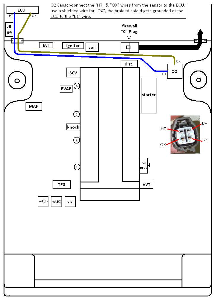
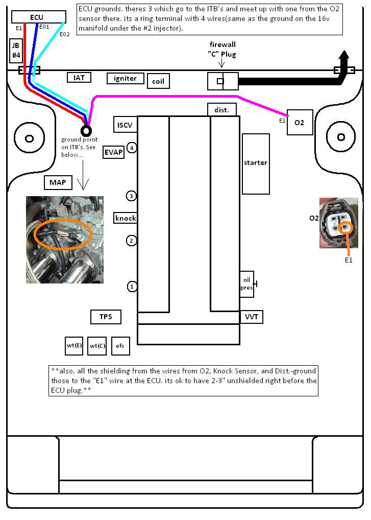
then the O2 sensor, the B+wire should already be done, so only the E1, HT, and OX wires left. you should use a shielded wire for the OX, this is like a braided metal netting that goes around the wire and keeps there from being any "interference" in the signal to the ECU. only thing is, you need to connect the shield to the E2 wire down by the ECU. if you bought a sacrificial harness, find out which wire is shielded and use that one. i will cover the "E1" wire later under "ecu grounds".
Image
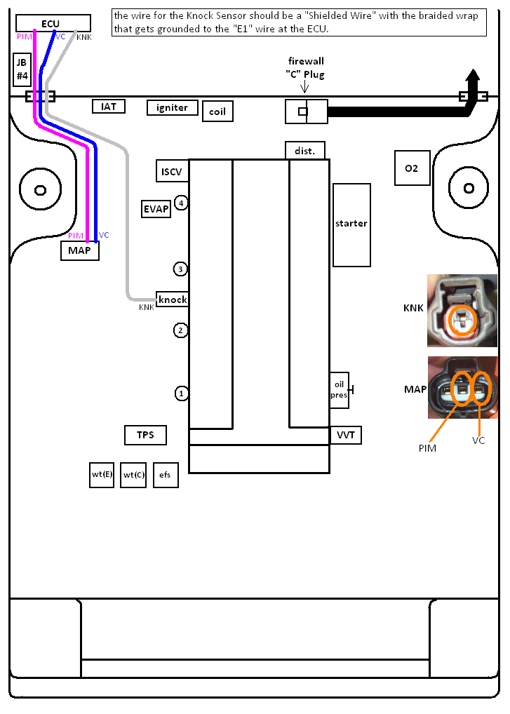
next work on the Knock Sensor and the MAP sensor to finish them up.
Image
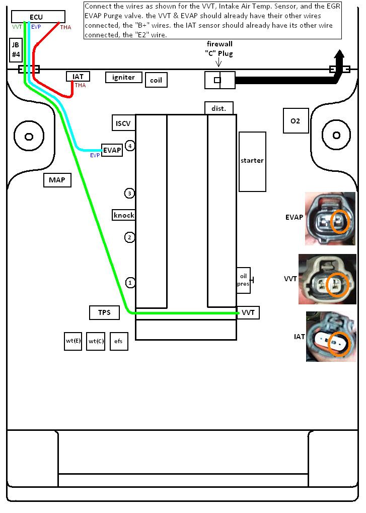
then finish up the the VVT solenoid, EVAP purge valve, and the Intake Air Temp. Sensor.
Image
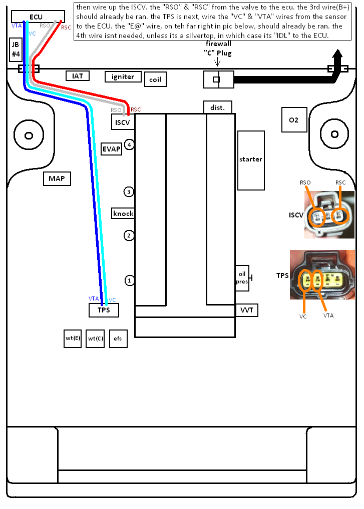
then connect the ISCV and the TPS. the TPS has 4 pin-outs, but the Blacktop only utilizes 3, while the Silvertop uses all 4.
Image
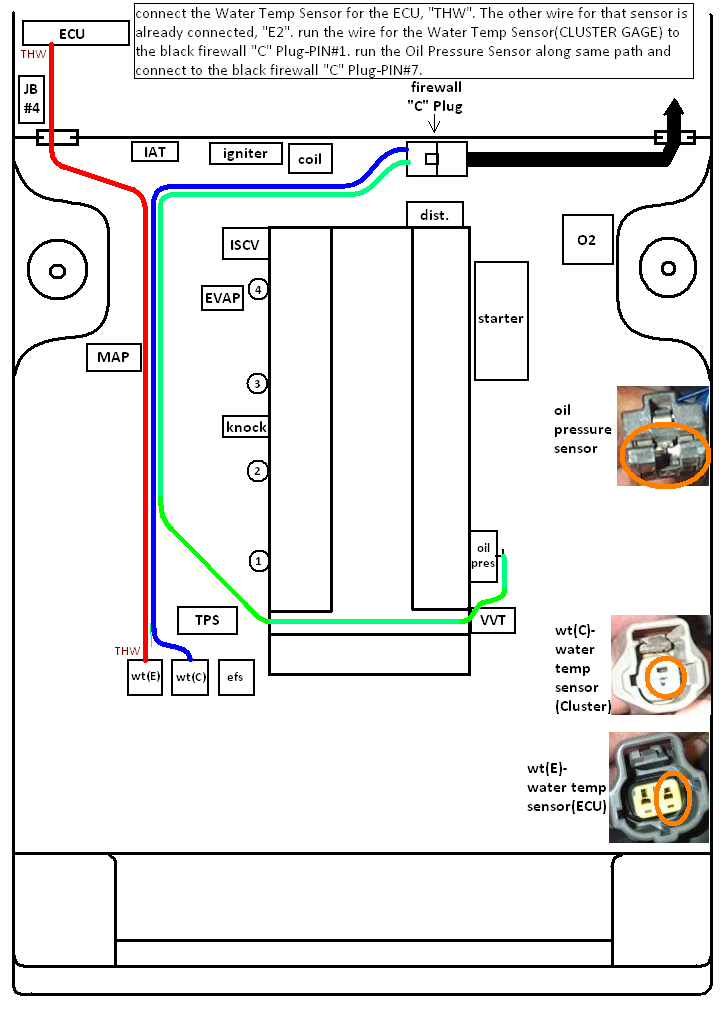
next is the ECU Water Temp Sensor"wt(E)", the Gage Cluster Water Temp Sensor"wt(C)", and the Oil Pressure Sensor wire. use the same wire from the 16v GTS harness if you want, just un-wrap the harness and pull it out so you dont have to solder it on the black firewall "C" Plug-PIN# 7. or just snip both ends and run a new wire.
Image
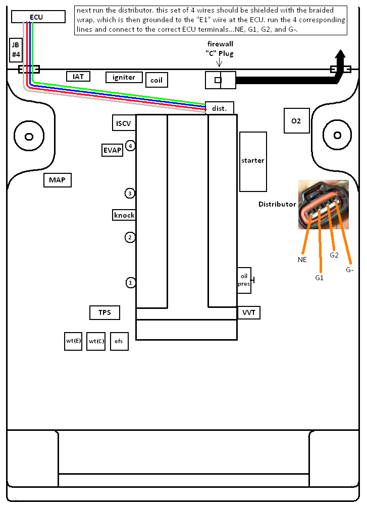
then there is the distributor. the 4 wires need to be shielded together with the braided wrap, then connect the shield to the "E1" wire at the ECU. i went to the junkyard and pulled apart a 1995 camry harness for this wire bundle, shielded and ready to go. it was about 8 inches too long so i shortened it. spent $10, and about 30 minutes of my times, and it came with the correct pigtail iirc.
Image
heres the grounds you need to hook up...
Image
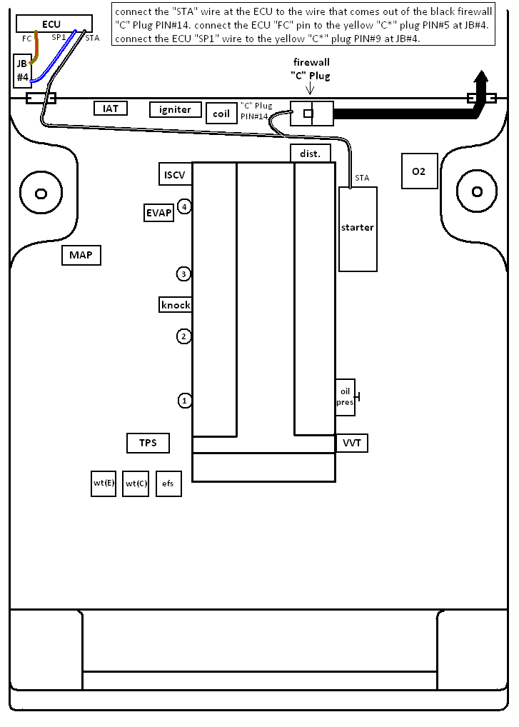
the starter power wire needs to be tapped into and ran to the ECU "STA" terminal, the "FC" terminal needs to be connected to the green/red wire of the COR, which can be accessed from the yellow "C*" Plug(pin#5) at the JB#4. and the "SP1" terminal at the same "C*" Plug too.
Image
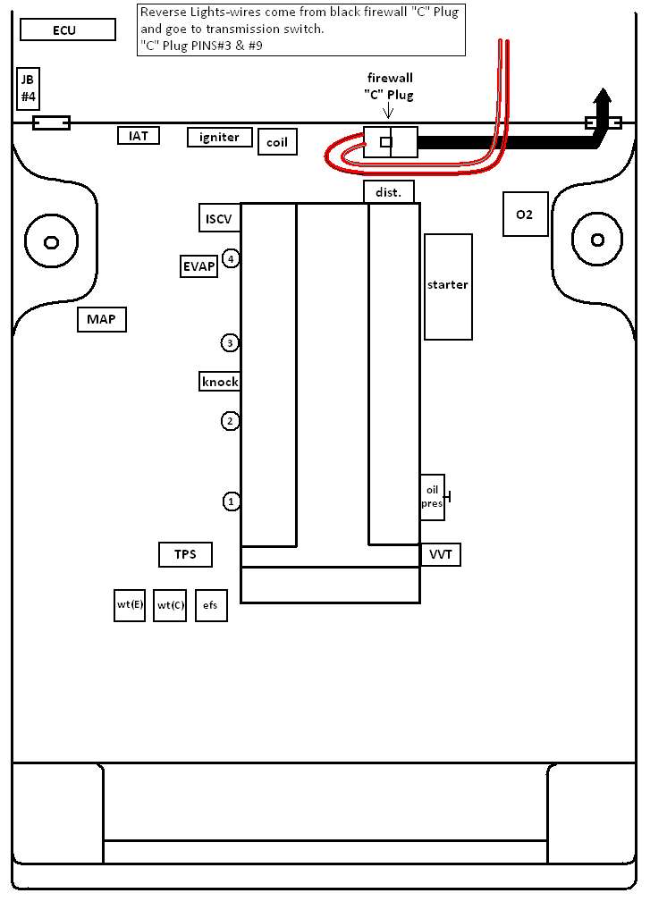
and the reverse light wires from the black firewall "C" Plug need to remain in tact...
Image
------------------------------------------------------------------------------------------------------------------
*just about all pigtail pics taken from the http://www.padandwheels.com site for reference, love that site...
------------------------------------------------------------------------------------------------------------------
more to be added as needed...
chances are i mixed a thing up or 2, if you see something wrong, let me know and ill fix it. likewise if i left anything out.
feel free to ask any questions, ill do my best to answer.
ENJOY!
morgan

User avatar
morgan
Member
Posts: 279
Joined: Thu Oct 18, 2012 11:28 am
Location: jersey

Re: my 20v'ed ae86 swap "how to" write-up

Post by morgan »

Extra Info...
Motor Mounts
theres a pin in the block that needs to be removed, its on the intake side, at the bottom. sometimes they are really stuck in there, just drill a hole in the motor mount then, so you can mount it if you can pull it out. in the pic below, the pin is circled in red, and the bolt holes for the motor mount are highlighted in green. the bottom pic, from the 4age20v blogsome site, just shows you how the motor mount should look once on the block.
Image
-----------------------------------------------------------------------------------------------------
How To De-Pin Connectors
not too difficult, here's some steps and tricks to doing it properly.

1-aquire a set of jewelers screwdrivers, you only really need on small flat head(size noted on case for the one I use.
Image
2-lets start with the ECU connectors, there's 2 types that I have seen.
here's the 1st type with a separate retainer clip in the connector itself. use the small screw driver and insert it into the 2 slots circled in blue, then pull the retainer up so the wire & terminal can be removed.
Image
3-here's the other type of connector, with 2 fold over retainers(one on the top, one on the bottom)
locking tabs circled, pull back retainers after releasing locking tabs(tabs are on both sides of the connector)
Image
4-fold over retainer connector opened up so terminals an be removed
Image
5-now its time to remove the wire & terminals. the openings are on top of the terminals, seen in pic, circled. that where the locking pin is located that you need to move up to unlock terminal.
Image
6-slide your flat head in the upper opening, sliding it along the top of the terminal till it stops(which should mean its up against the locking pin) then rotate the screw driver to move locking pin up as you pull wire out from the back. watch how the terminal is orientated once you pull it out, you should see a large opening on the top of it, that's where the locking pin is inserted to keep terminal in the connector. obviously, it needs to go back the same way, it won't go in any other way without force and damaging the connector.
Image
-----------------------------------------------------------------------------------------------------
now a look at some other connectors...

Junction Block Connector
7-here's a larger connector, similar to one of the ECU connectors, release the retainer by prying it up prior to removing the wire & terminals in the same fashion.
Image
-----------------------------------------------------------------------------------------------------
Sensor Connectors
8-these can prove a bit more difficult. 99% of the time there's an inner retainer. the connector is grey, while the retainer is black.
Image
9-use the flat head and pry the retainer up and out of the connector. some are harder than others and some will break so you might need extras(generally the 20v ECu Water Temp. connector is the one I break...every time).
Image
10-after you release the retainer, pull it out of the connector.
Image
11-follow the same steps as the ECU connectors for releasing the locking pin and pulling the wire & terminals out.
Image
-----------------------------------------------------------------------------------------------------
I made a little sketch so you can see what's going on inside the connector with the retainer and locking pins.
Image

***when inserting the terminals back into the connector, usually you will feel the locking pin snap back into place. done forget to re-install the retainer afterwards.***
Last edited by morgan on Thu Jan 16, 2014 1:16 pm, edited 1 time in total.

joel26
VIP Member
Posts: 2069
Joined: Wed Jan 23, 2008 10:30 pm
Location: Spring Tx
Contact:

Re: my 20v'ed ae86 swap "how to" write-up

Post by joel26 »

Nice write up
Image

User avatar
GamblerZ
Member
Posts: 495
Joined: Sat Oct 02, 2010 2:15 pm
Location: West Texas
Contact:

Re: my 20v'ed ae86 swap "how to" write-up

Post by GamblerZ »

This thread should be converted into a PDF for download here on the site. That way he won't have to worry about keeping the pictures hosted/current 2 years down the road.
'85 Toyota Corolla GT-S Hatchback DMG
'92 Lexus SC400 Diamond White Pearl (WTS/WTT)
'99 Lexus SC300 Millenium Silver Metallic (WTS)

dr.occa
Hades - Site Admin
Posts: 7733
Joined: Tue Sep 04, 2007 1:49 pm
Location: On my hiney...in HOU
Contact:

Re: my 20v'ed ae86 swap "how to" write-up

Post by dr.occa »

Well, it'll eventually find its way into printed format right Craig.

User avatar
morgan
Member
Posts: 279
Joined: Thu Oct 18, 2012 11:28 am
Location: jersey

Re: my 20v'ed ae86 swap "how to" write-up

Post by morgan »

I'll see what I can do...

User avatar
morgan
Member
Posts: 279
Joined: Thu Oct 18, 2012 11:28 am
Location: jersey

Re: my 20v'ed ae86 swap "how to" write-up

Post by morgan »

updated to include a "connector de-pinning guide"

Post Reply